Wi-Fi Car Robotics Kit Manual
Learn electronics, programming, and robotics by building your own Wi-Fi controlled car!
Welcome & Introduction
Welcome to the Wired Circuit Wi-Fi Car Robotics Kit! This kit is designed for kids and beginners to explore the world of robotics using Wi-Fi-enabled microcontrollers. You'll learn about electronics, programming, and how to build and control your own car wirelessly!
Box Contents
Main Components
- NodeMCU (ESP8266)
- Motor Driver (L298N / Custom)
- 2 DC Motors
Structural Parts
- Aluminum Chassis
- Wheels (x2)
- Mounting hardware (screws, nuts, etc.)
Power & Connectivity
- Battery holder and switch
- USB cable
- Jumper wires
Assembly Instructions
- Mount the motors to the chassis using the provided screws.
- Fix the motor driver on the top plate of the chassis using screws and standoffs.
- Attach the wheels to the motor shafts, ensuring they're firmly secured.
- Connect NodeMCU to the motor driver following the circuit diagram in the next section.
- Insert the batteries into the holder and connect to the power switch.
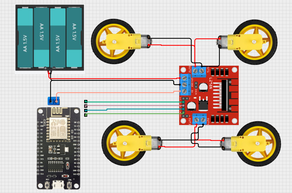
Circuit Diagram
Follow this diagram to connect the NodeMCU to the Motor Driver and power system:
| NodeMCU Pin | Motor Driver Connection | Function |
|---|---|---|
| D1 | IN1 | Motor A Direction 1 |
| D2 | IN2 | Motor A Direction 2 |
| D3 | IN3 | Motor B Direction 1 |
| D4 | IN4 | Motor B Direction 2 |
| GND | GND | Common Ground |
| VIN | 5V (If needed) | Power Supply (Optional) |
Programming Guide
Setup Steps
- Install Arduino IDE from arduino.cc
- Install NodeMCU board package via Boards Manager
- Connect NodeMCU to your computer via USB
- Select the correct board and port in Arduino IDE
- Upload the sample code provided below
Sample Code
#include
#include
// Wi-Fi credentials
const char* ssid = "WiFi-Car";
const char* password = "password123";
// Motor pins (Using common GPIO numbers for NodeMCU)
// Adjust these pins based on your specific NodeMCU board layout if needed
const int motor1Pin1 = D1; // GPIO 5
const int motor1Pin2 = D2; // GPIO 4
const int motor2Pin1 = D3; // GPIO 0
const int motor2Pin2 = D4; // GPIO 2
// Create web server on port 80
ESP8266WebServer server(80);
// --- Function Declarations ---
void handleRoot();
void handleForward();
void handleBackward();
void handleLeft();
void handleRight();
void handleStop();
void stopMotors();
void moveForward();
void moveBackward();
void turnLeft();
void turnRight();
// --- Setup Function ---
void setup() {
// Initialize serial communication for debugging
Serial.begin(115200);
Serial.println("\nWiFi Car Setup");
// Set motor control pins as outputs
pinMode(motor1Pin1, OUTPUT);
pinMode(motor1Pin2, OUTPUT);
pinMode(motor2Pin1, OUTPUT);
pinMode(motor2Pin2, OUTPUT);
// Ensure motors are stopped initially
stopMotors();
Serial.println("Motors Initialized and Stopped.");
// Set up NodeMCU as a Wi-Fi Access Point
Serial.print("Setting up Access Point...");
WiFi.softAP(ssid, password);
Serial.println(" Done.");
IPAddress apIP = WiFi.softAPIP();
Serial.print("AP IP address: ");
Serial.println(apIP);
// Define server routes (web page handlers)
server.on("/", HTTP_GET, handleRoot); // Main control page
server.on("/forward", HTTP_GET, handleForward);
server.on("/backward", HTTP_GET, handleBackward);
server.on("/left", HTTP_GET, handleLeft);
server.on("/right", HTTP_GET, handleRight);
server.on("/stop", HTTP_GET, handleStop);
// Start the web server
server.begin();
Serial.println("HTTP server started. Ready for connections.");
}
// --- Main Loop ---
void loop() {
// Handle incoming client requests
server.handleClient();
}
// --- Web Page Handlers ---
void handleRoot() {
// Send the HTML control page to the client
// NOTE: This C++ string contains the HTML for the car's control interface
String html = R"rawliteral(
WiFi Car Control
WiFi Car Control
)rawliteral";
server.send(200, "text/html", html);
}
void handleForward() {
Serial.println("Command: Forward");
moveForward();
server.send(200, "text/plain", "OK");
}
void handleBackward() {
Serial.println("Command: Backward");
moveBackward();
server.send(200, "text/plain", "OK");
}
void handleLeft() {
Serial.println("Command: Left");
turnLeft();
server.send(200, "text/plain", "OK");
}
void handleRight() {
Serial.println("Command: Right");
turnRight();
server.send(200, "text/plain", "OK");
}
void handleStop() {
Serial.println("Command: Stop");
stopMotors();
server.send(200, "text/plain", "OK");
}
// --- Motor Control Functions ---
void stopMotors() {
digitalWrite(motor1Pin1, LOW);
digitalWrite(motor1Pin2, LOW);
digitalWrite(motor2Pin1, LOW);
digitalWrite(motor2Pin2, LOW);
}
void moveForward() {
digitalWrite(motor1Pin1, HIGH); // Motor 1 Forward
digitalWrite(motor1Pin2, LOW);
digitalWrite(motor2Pin1, HIGH); // Motor 2 Forward
digitalWrite(motor2Pin2, LOW);
}
void moveBackward() {
digitalWrite(motor1Pin1, LOW);
digitalWrite(motor1Pin2, HIGH); // Motor 1 Backward
digitalWrite(motor2Pin1, LOW);
digitalWrite(motor2Pin2, HIGH); // Motor 2 Backward
}
void turnLeft() {
// Turn left: Motor 1 Backward, Motor 2 Forward (Tank steer)
digitalWrite(motor1Pin1, LOW);
digitalWrite(motor1Pin2, HIGH);
digitalWrite(motor2Pin1, HIGH);
digitalWrite(motor2Pin2, LOW);
}
void turnRight() {
// Turn right: Motor 1 Forward, Motor 2 Backward (Tank steer)
digitalWrite(motor1Pin1, HIGH);
digitalWrite(motor1Pin2, LOW);
digitalWrite(motor2Pin1, LOW);
digitalWrite(motor2Pin2, HIGH);
}
Make sure to install the required Arduino libraries:
- ESP8266WiFi
- ESP8266WebServer
Also ensure the motor control functions (stopMotors(), moveForward(), etc.) match your specific motor driver wiring and logic.
Wi-Fi Setup
After uploading the code, power the NodeMCU and connect to the Wi-Fi network:
Connect to AP Mode (Default)
- On your phone/computer, look for a Wi-Fi network named "WiFi-Car".
- Connect to it using the password "password123".
- Open a web browser and navigate to the IP address
192.168.4.1. - Use the buttons on the web page to control the car. Press and hold direction buttons, release to stop.
Use Home Network (Advanced)
- Modify the Arduino code: comment out `WiFi.softAP(...)` and uncomment/add `WiFi.begin("Your_Home_SSID", "Your_Home_Password");`.
- Replace `"Your_Home_SSID"` and `"Your_Home_Password"` with your actual Wi-Fi credentials.
- Add code to wait for connection (`while (WiFi.status() != WL_CONNECTED)`) and print the assigned IP address (`Serial.println(WiFi.localIP());`).
- Upload the modified code.
- Connect your control device (phone/computer) to your home Wi-Fi network.
- Find the car's IP address (check Serial Monitor via USB) and navigate to that IP in your browser.
How It Works
The Wi-Fi Car operates through a series of connected components working together:
NodeMCU (ESP8266)
Acts as the brain. It runs the Arduino code, creates a Wi-Fi access point (or connects to your network), hosts a simple web server, and sends digital HIGH/LOW signals to the motor driver based on commands received via Wi-Fi.
Motor Driver (L298N)
The L298N driver takes the low-current logic signals from the NodeMCU's GPIO pins (D1-D4) and uses them to switch the higher current from the battery pack to the motors. It allows control over the direction of each motor.
Web Interface
The HTML page (defined inside the Arduino code's `handleRoot()` function) is sent to your browser when you connect. Buttons on this page use simple JavaScript (`fetch`) to send HTTP GET requests (like `/forward`, `/stop`) back to the NodeMCU's IP address. The server running on the NodeMCU receives these requests and triggers the corresponding motor functions.
Troubleshooting
| Issue | Possible Cause | Solution |
|---|---|---|
| Cannot find "WiFi-Car" network | NodeMCU not powered; Code upload failed; Incorrect code running; Antenna issue (less likely) | Check power supply to NodeMCU (USB or VIN). Re-upload the correct code. Check Arduino IDE console for upload errors. Open Serial Monitor (115200 baud) to see setup messages or errors. |
Connected to Wi-Fi, but 192.168.4.1 doesn't load/respond |
Web server failed to start; Device issue (firewall, browser cache); IP address conflict (rare) | Check Serial Monitor for "HTTP server started" message. Try clearing browser cache or using a different device/browser. Ensure your device obtained an IP from the NodeMCU (e.g., 192.168.4.x). |
| Motors don't spin at all | Wiring error (GPIO to IN pins, Motor to OUT pins, Power to Driver); Low/dead battery; Motor driver not powered (VM/VCC, GND); ENA/ENB disabled (if using L298N with jumpers removed) | Triple-check all connections based on the circuit diagram. Use fresh batteries. Ensure correct voltage (e.g., 5-9V) is supplied to the motor driver's VM terminal. Ensure GNDs are connected. If L298N jumpers for ENA/ENB are removed, ensure those pins are driven HIGH by NodeMCU (or add jumpers back). |
| Motors spin weakly or only one motor spins | Low battery power; Poor connection; Motor failure | Replace batteries. Check for loose jumper wires. Test motors individually by applying battery voltage directly (briefly!). |
| Car moves in wrong direction | Motor wires reversed on one/both motors; Logic error in motor control functions | Swap the two wires for the motor(s) going the wrong way at the motor driver output terminals OR modify the HIGH/LOW combinations in the `moveForward()`, `moveBackward()`, `turnLeft()`, `turnRight()` functions in the Arduino code. |
| Code Upload Fails (Error in IDE) | Incorrect COM port selected; Driver missing (CH340/CP210x); NodeMCU not in Bootloader Mode; USB cable is power-only (no data); Wiring conflict (GPIO0 pulled HIGH) | Select the correct Port under Tools menu. Install USB-to-Serial drivers. Press and hold FLASH/BOOT button, tap RESET button, then release FLASH/BOOT just as upload starts. Try a different USB cable. Temporarily disconnect wires from D3 (GPIO0) during upload. |
| Motor driver chip (L298N) gets very hot | Short circuit (motor wires touching, faulty motor); Overloading (motors draw too much current); Incorrect voltage | Immediately disconnect power! Check motor wiring for shorts. Ensure motor voltage rating matches supply. Consider if motors are stalled. |
Add-Ons & Upgrades
Line Following
Add infrared (IR) line tracking sensors (like TCRT5000 modules) connected to NodeMCU analog/digital pins. Modify the code to read sensor values and adjust motor movements to follow a line.
Learn MoreObstacle Avoidance
Mount an ultrasonic sensor (HC-SR04). Connect Trigger and Echo pins to NodeMCU GPIOs. Add code to measure distance and stop/turn the car if an obstacle is detected within a certain range.
Learn MoreSpeed Control (PWM)
Remove ENA/ENB jumpers on the L298N. Connect NodeMCU PWM-capable pins (e.g., D5, D6) to ENA/ENB. Use `analogWrite(pin, value)` (0-1023 for ESP8266) in the code to control motor speed. Add speed controls to the web interface.
Learn MoreProject Showcase
Share your completed project with our community! Submit photos and videos of your Wi-Fi Car in action.
How to Submit
- Take clear photos or a short video (max 1 min) of your assembled and working car.
- Briefly describe any modifications, challenges, or addons you implemented.
- Email materials to [email protected] (replace with actual email) with the subject "WiFi Car Showcase".
- Alternatively, post on our Community Forum (link needed).
Support & Contact
Need help with your Wi-Fi Car Robotics Kit? We're here to assist you!
Email Support
For technical assistance:
Response typically within 24-48 business hours.
Community Forum
Ask questions and share solutions with others:
Monitored by staff and experienced users.
Certification & Resources
Expand your knowledge and get recognized for completing the project.
Documentation Links
Code Repository
Project Certification
Showcase your skills! To earn a digital certificate:
- Successfully build and control the basic Wi-Fi Car.
- Implement at least one addon (e.g., sensors, speed control).
- Submit video proof and your code via the application form.